
This video very briefly describes every detail of tool offset setting or tool setup on CNC Lathe with Siemens Sinumerik 808D cnc control.
As actual selection of tools and how to mount tools to turret of lathe machine is described in a previous video tutorial Tool Setup on Machine – Sinumerik 808D Video Tutorial Turning Part 5
Although this machine doesn’t have a tool measuring probe inside machine, but this video shows how to take tool measurements by using machine built-in tool measurement system (Siemens call it – Tool measuring screen),
Such tool and work offset measuring system is found in multiple other cnc machines, this makes tool offset setting & work offset setting procedure easy and accurate.
Contents
Sinumerik 808D Tool Offset Setting Step by Step Procedure
The step by step procedure for manual tool setup is given below,
1 – Press Offset-Area button (for tool list).
2 – Press soft-key New-Tool to create a new tool.
3 – Type the tool number (for example 1) and press OK to confirm.
3.1 – After this a list will appear with tool data like X-length, Z-length, tip-radius, tip-width and tool-type.
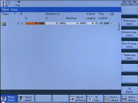
Sinumerik 808D Tool List
3.2 – Enter tip-radius and tip-width (if applicable), as other tool dimensions are not known yet.
4 – Press machine-area key on the control.
5 – Select Jog mode from the machine control panel.
5.1 – Now bring the respective tool in cutting position by pressing TSM button, enter tool number and then press Cycle Start button.
5.2 – Start spindle by pressing TSM, enter Spindle speed (RPM) and rotation direction (M3) and press Cycle Start.
6 – Choose Handwheel mode on machine control panel.
Tool Offset Setting in X-Axis
7 – With the help of Handwheel bring the tool near the already gripped component in cnc machine.
7.1 – Cut a diameter (any diameter) nearly 10mm long.
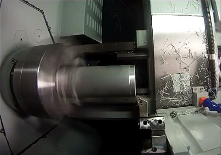
Sinumerik 808D Tool X-Length Measurement Procedure
7.2 – Move tool away from component only in Z-axis (don’t move tool in X-axis)
8 – Stop spindle by pressing Reset button on machine control panel.
9 – Press Measure-tool soft-key, followed by the Measure-X soft-key.
9.1 Measure diameter accurately (already cut in step 7.1)
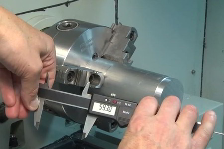
Measure diameter for X length
9.2 Enter measured value in Diameter-window (tool measuring screen)
9.3 Press Set-length-X soft-key.
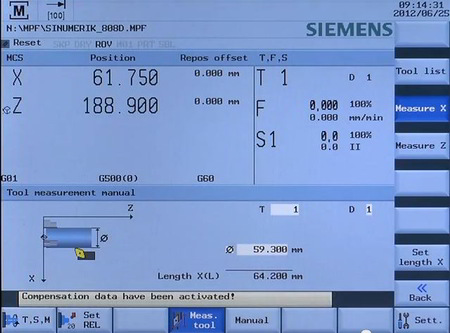
Sinumerik 808D Tool Measuring Screen
Geometry X for turning tool is now set
Tool Offset Setting in Z-Axis
10 – Start spindle by pressing TSM, enter Spindle speed (RPM) and rotation direction (M3) and press Cycle Start.
11 – With the help of Handwheel bring the tool again near the already gripped component in cnc machine.
11.1 – Cut across the front-face of component.
11.2 – Move tool away from component only in X-axis (don’t move tool in Z-axis)
11.3 – Stop spindle by pressing Reset button on machine control panel.
12 – Press Measure-tool soft-key, followed by the Measure-Z soft-key.
12.1 Press Set-length-Z soft-key.
Geometry Z for turning tool is now set.
The same procedure can be applied to threading and plunging tools for tool offset setting.


