
Fadal G Codes M Codes Fixed Subroutines etc. for cnc machinists who work on Fadal VMCs.
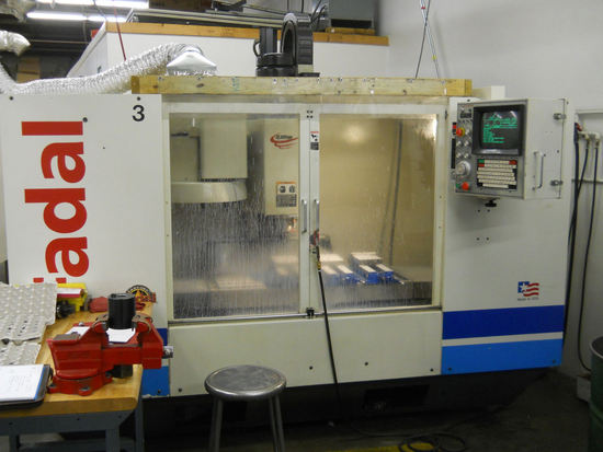
G Codes
| G code | Description |
|---|---|
| G0 | Rapid Travel |
| G1 | Linear Interpolation |
| G2 | Circular Interpolation (Clockwise) |
| G3 | Circular Interpolation (Counter Clockwise) |
| G4 | Dwell P= Time in Milliseconds Also: Non Modal In-position Check |
| G5 | Non Modal Rapid Travel |
| G8 | Accelerate (No Feed Ramps) |
| G9 | Decelerate (Feed Ramps) Also: In Position Check |
| G10 | Programmable Data Input L02= Fixture X, Y, Z, A, B, P= 0, 1-48 L10= Length, P= 1-99, R0= Amount L12= Diameter, P= 1-99, R0= Amount L13= Read Fixture, P= 1-24, R0= Z, R1= X, R2= Y L14= Read Length, P= 1-99, R0= Amount L15= Read Diameter, P= 1-99, R0= Amount L100 to L109= R Values, P= Amount |
| G15 | YZ Circular Interpolation with the A Axis |
| G17 | XY Plane Selection Also: Y Axis Cam Wrapping Q= A Axis Ratio/ [5p (cam dia. in inches)] Q= A Axis Ratio/ [(5/25.4p (cam dia. in mm)] P0= A Axis, P1= B Axis |
| G17.1 | A/B Word Swap On |
| G17.2 | A/B Word Swap Off |
| G18 | ZX Plane |
| G19 | YZ Plane |
| G20 | Check for Inch Parameter Setting |
| G21 | Check for Metric Parameter Setting |
| G28 | Return to Zero |
| G28.1 | Return from Jog Away |
| G29 | Return from Zero |
| G31 | Probe Touch Function |
| G31.1 | Probe No Touch Function |
| G40 | Cutter Radius Compensation Cancel |
| G41 | Cutter Radius Compensation Left (climb) |
| G42 | Cutter Radius Compensation Right (conve.) |
| G43 | Tool Length Compensation Positive |
| G44 | Tool Length Compensation Negative |
| G45 | Tool Length Offset Single Expansion |
| G46 | Tool Length Offset Single Reduction |
| G47 | Tool Length Offset Double Expansion |
| G48 | Tool Length Offset Double Reduction |
| G49 | Tool Length Offset Cancel |
| G50 | Ramp Slope Control Cancel |
| G50.1 | Mirror Image Cancel |
| G51 | Ramp Slope Control R0= Ramp Speed Value of .5 – 2. R0+= Z Axis, R0-= XY Axis |
| G51.1 | Mirror Image |
| G51.2 | Tool Load Compensation State Feed Rate Before the G51.2 Line R1= Target Spindle Load R2= Min. Percentage Feed Rate Reduction R3= Max. Percentage Feed Rate Increase R4= Time at Min. Feed Rate to Initiate Slide Hold |
| G51.3 | Axis Scaling R1= Program (All three axes) R2= X R3= Y R4= Z |
| G52 | Coordinate System Shift |
| G53 | Use Machine Coordinate System |
| G54-59 | Fixture Offsets 1-6 G66 Modal Subroutine Call G67 Modal Subroutine Cancel G68 Rotation (R0= Angle, XY= Center of Rotation) G69 Rotation Cancel G70 Check for Inch Parameter G71 Check for Metric Parameter |
| G73 | Peck Drill Q= Peck Size P= Feed Distance before next Peck (optional) I= Initial Peck J= Reducing Value for Subsequent Pecks K= Minimum Peck Size |
| G74 | Left Hand Tap Format 1 Q= Thread Lead (1/pitch), F= RPM Format 2 S= RPM, F= Feed (Lead * RPM) |
| G74.1 | Left Hand Rigid Tap Format 1 Q= Thread Lead (1/pitch), F= RPM Format 2 S= RPM, F= Feed (Lead * RPM) |
| G74.2 | Prepare for G74.1 |
| G75 | Tapping Head Cycle Format 1 Q= Thread Lead (1/pitch), F= RPM Format 2 S= RPM, F= Feed (Lead * RPM) |
| G76 | Fine Boring Q= Amount of Y+ Shift or I= Amount & Direction of X Shift J= Amount & Direction of Y Shift |
| G80 | Fixed Cycle Cancel |
| G81 Drill, Spot Drill | |
| G82 | Center Drill, Counterbore P= Dwell Time in Milliseconds 180,000/RPM= Dwell time for 3 revolutions |
| G83 | Deep Hole Cycle Q= Peck Size P= Feed Distance before next Peck (optional) I= Initial Peck J= Reducing Value for Subsequent Pecks K= Minimum peck Size |
| G84 | Right Hand Tap Format 1 Q= Thread Lead (1/pitch), F= RPM Format 2 S= RPM, F= Feed (Lead * RPM) |
| G84.1 | Right Hand Rigid Tap Format 1 Q= Thread Lead (1/pitch), F= RPM Format 2 S= RPM, F= Feed (Lead * RPM) |
| G84.2 | Prepare for G84.1 |
| G85 | Bore In / Out |
| G86 | Bore In / Spindle Off / Rapid Out |
| G87 | Bore In / Out |
| G88 | Bore In / Dwell / Out, P= Milliseconds |
| G89 | Bore In / Dwell / Out, P= Milliseconds |
| G90 | Absolute Positioning |
| G91 | Incremental Positioning |
| G91.1 | High Speed Execution (-2 System Only) |
| G91.2 | High Speed Execution Cancel Also: Binary Compress / Analyzer End Point |
| G91.3 | Binary Compress / Analyzer Start Point |
| G92 | Absolute Preset |
| G93 | 1/T Feed Rate Specification (Inverse Time) |
| G94 | Feed Rate Specification DPM, IPM |
| G98 | Return to Initial Plane |
| G99 | Return to R0 Clearance Plane |
M Codes
| M code | Description |
|---|---|
| M0 | Program Stop |
| M1 | Optional Stop |
| M2 | End of Program |
| M3 | Spindle On Clockwise |
| M3.1 | Sub–Spindle On Ignore Magnet CW |
| M3.2 | Acknowledge Spindle Magnet |
| M4 | Spindle On Counter Clockwise |
| M4.1 | Sub–Spindle On Ignore Magnet CCW |
| M4.2 | Acknowledge Spindle Magnet |
| M5 | Spindle Off |
| M6 | Tool Change |
| M7.1 | Servo Coolant On |
| M8 | Coolant On |
| M8.1 | Servo Coolant On |
| M9 | Coolant Off |
| M10 | Cancel Reciprocation |
| M11 | X Axis Reciprocation |
| M12 | Y Axis Reciprocation |
| M13 | Z Axis Reciprocation |
| M14 | B Axis Reciprocation |
| M15 | A Axis Reciprocation |
| M16 | C Axis Reciprocation |
| M17 | End of Subroutine |
| M18 | Cycle Cushman Indexer |
| M19 | Spindle Stop/Orient |
| M20 | Cycle General Purpose Indexer Also: Automatic Doors Close Also: Toggle On/Off Hydrosweep |
| M30 | End of all Subroutines Also: End of Program (Format 2) |
| M31 | Exchange Pallets |
| M32 | Store/Load Pallet A |
| M32.1 | Load and Verify Pallet A |
| M33 | Store/Load Pallet B |
| M33.1 | Load and Verify Pallet B |
| M41 | Low Range RPM |
| M42 | High Range RPM |
| M45 | Execute Fixed Cycle |
| M46 | Positive Approach On |
| M47 | Cancel Positive Approach |
| M48 | Feed Rate and RPM Pot Active |
| M48.1 | Servo Coolant Pot Active |
| M48.2 | Dual Rotary Pot Active Pallet A |
| M48.3 | Dual Rotary Pot Active Pallet B |
| M49 | Feed Rate and RPM Pot Inactive |
| M49.1 | Servo Coolant Pot Inactive |
| M49.2 | Dual Rotary Pot Inactive Pallet A |
| M49.3 | Dual Rotary Pot Inactive Pallet B |
| M60-69 | User Attached Devices M60 A Axis Brake On M65 TS-20 Probe Active M61 A Axis Brake Off M66 MP-12 Probe Active M62 B Axis Brake On M67 Laser Probe Active M63 B Axis Brake Off M68 Delta Motor M64 MP Probe Active M69 Wye Motor |
| M80 | Automatic Doors Open |
| M81 | Automatic Doors Close |
| M90 | Default Gain (from SV Command) |
| M90.1 | Advanced Feed Forward Gain Enable P=Gain (50-250) |
| M91 | Normal Gain |
| M92 | Intermediate Gain |
| M94 | Feed Forward P= Angle Tolerance Q= Line Length (Moves less than this not checked) Example: M94 P91 Q.002 |
| M94.1 | Feed Forward by Feed Rate Modification State Feed Rate Before M94.1 Line P= Angle Q= Percentage change each modification R0+= Min. Feed Rate Modification R1+= Length to ignore M94.1 R2+= Modify feed every, this angle, from P Example: M94.1 P170 Q10. R0+50. R1+1. R2+15. |
| M94.2 | Advanced Feed Forward On, P= Ramp, Q= Detail Window |
| M95 | Feed Forward Cancel |
| M95.1 | Feed Forward Modify Cancel |
| M95.2 | Advanced Feed Forward Cancel |
| M96 | Roll CRC |
| M97 | Intersectional CRC |
| M98 | Execute Sub Program P= Program # L= # of Repetitions |
| M99 | End of Sub Program Also: Line Jump, P= Line #, Example: M99 P# |
Fixed Subroutines
| Subroutines | Description/Parameters |
|---|---|
| L9101 | Probe Functions R1+1-10, See User’s Manual for details |
| L9201 | Engraving: R1+0= Standard font R1+1= Stencil font R1+2= Serialized standard R1+3= Serialized stencil R2+= Height of letters R3+= Angle of word R4+= Serial increment R0= Clearance plane Z= Final depth F= Feed rate |
| L93NN | Bolt Circle R0= 1 (incremental X distance and direction from 1st position to center) R1= J (incremental Y distance and direction from 1st position to center) R2= Angular step between holes (+ angles for CCW, – angles for CW) NN= Amount of holes |
| L94NN | Mill Boring cycle CCW: R0+= Feed, R1+= Diameter of hole, NN= Repetitions |
| L95NN | Mill Boring cycle CW: R0+= Feed, R1+= Diameter of hole, NN= Repetitions |
| L9601 | Rectangular pocket CCW: R0+= Feed, R1+= Corner radius on tool, R2+= X, R3+= Y |
| L9701 | Rectangular pocket CW: R0+= Feed, R1+= Corner radius on tool, R2+= X, R3+= Y |
| L9801 | Circular pocket CCW: R0+= Feed, R1+= Corner radius on tool, R2+= Diameter of hole |
| L9901 | Circular pocket CW: R0+= Feed, R1+= Corner radius on tool, R2+= Diameter of hole |
NC Word Summary
| NC Word Summary | Definition |
|---|---|
| A | A axis angular motion command (or optional Servo Coolant) |
| B | B axis angular motion command |
| C | C axis angular motion command |
| D | Tool diameter offset |
| E | Fixture offset |
| F | Feed rate, or spindle speed for tapping |
| G | Preparatory function |
| H | Tool length offset or Length and diameter offset for Format 1 |
| I | X axis distance to arc center or Initial peck size for drilling (G73 G83) or X axis shift in boring cycle (G76) JY axis distance to arc center or Reducing value of the initial peck (G73, G83) or Y axis shift in boring cycle (G76) |
| J | Y axis distance to arc center or Reducing value of the initial peck (G73, G83) or Y axis shift in boring cycle (G76) |
| K | Z axis distance to arc center or Minimum peck size for drilling (G73, G83) |
| L | Subroutine definition or call or Subprogram repeat function (M98) or Programmable data input function (G10) or Line repeat function or Fixed cycle repetitions |
| M | Machine function code |
| N | Program sequence number |
| O | Program identification number |
| P | Dwell time in milliseconds (G04) or Percentage factor for retracting feed on tapping cycles or Fixture and tool offset number (G10) or Subprogram number (M98) or Value for R0-R9 (G10) or Sequence/ line number jump (M99) or Feed distance before peck (G73 G83) or P1 with G17 Q to use B axis during mapping or Angular tolerance for Feed Forward |
| Q | Peck size in drill cycles (G73, G83) or Thread lead in tapping cycles (G74, G75, G84) or Diameter for automatic tool diameter override (H99) or Scale factor for Flat Cam programming on the rotary table or Length tolerance to ignore Feed Forward |
| R | Subroutine parameter input R0 through R9 R0 Plane for fixed cycle or Radius designation (circular interpolation, G2 & G3) or Tool offset value amount (G10) Parametric Variables R0, R1 – R9 |
| S | Spindle speed (RPM) |
| S.1 | Set belt range to low |
| S.2 | Set belt range to high |
| T | Tool number selector for turret |
| V | Variables in Macros (V1-V100) |
| X | X axis motion command |
| Y | Y axis motion command |
| Z | Z axis motion command |
Character Summary
| Character | Definition |
|---|---|
| 0-9 | Numerical digits |
| A-Z | Alphabetical characters |
| % | Program start or end, rewind to start |
| + | Plus, positive |
| – | Minus, negative |
| ( | Comment start (standard NC program), or Engraving text start (L9201 Fixed Subroutine), or Mathematical operator (Macro Programming) |
| . | Decimal point |
| , | Comma |
| EOB | ENTER key, carriage return / line feed (ASCII 13,10) |
| * | Comment start |
| / | Optional block skip |
| : | Program identification number (Format 2) |
| # | Macro Line Identification |


