2nd part of Circular Interpolation Concepts & Programming series, this article explains the required information to program/machine circular interpolation on a cnc machine, and how cnc machinists can program circular interpolation with the R (radius).
Read Other Parts of this Article
- Circular Interpolation Concepts & Programming Part 1 (Concepts)
- Circular Interpolation Concepts & Programming Part 2 (Use of R)
- Circular Interpolation Concepts & Programming Part 3 (Use of I J K)
- Circular Interpolation Concepts & Programming Part 4 (Unknown R)
- Circular Interpolation Concepts & Programming Part 5 (Examples)
- Circular Interpolation Concepts & Programming Part 6 (Uses & Exercises)
FIVE PIECES OF INFORMATION
Five pieces of information are required for executing a circular interpolation command.
Circular Motion
| Item | Command |
|
|
|
|
|
|
|
|
|
|
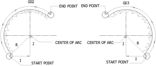
With the help of above information we can easily say that there are two ways to specify the center of the circular arc that you rotating around.
- Uses of R to specify the radius of the arc.
- Uses of I, J, or K to specify the distance from the starting point to the center of the arc.
USES OF R
The first method is very simple and there is no extra ordinary effort is required to program an Arc or Circle. Just mention the next point values of X, Y coordinate and use R+“value”. For many arc programming projects, the direct radius can be used with the R address, available for majority of control systems. In this case, the angular difference between the start and end points is very important, because the computer will do its own calculations to find the arc center. The arc with the angular difference of 180⁰ or less measured between the start and end points, uses an R positive value. The arc, in which the angular difference is more than 180⁰, uses an R negative value.
For example: see the following picture
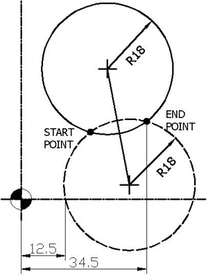
Radius Positive Negative
In the above picture, there are two circles. One is dash line circle and the other is solid. These two circles are intersecting with each other at two points which are shown in black dots.
If the tool motion of dash circle is clockwise from start point to end point than the arc is less than 180⁰. The code for this motion of tool in absolute mode G90 will look like this.
G02 X34.5 Y20 R18 F100.
And if the tool motion of solid circle is clockwise from start point to end point than the arc is more than 180⁰. The code for this motion of tool in absolute mode G90 will look like this.
G02 X34.5 Y20 R-18 F100.
When circular interpolation command is activated by a CNC program, any currently active tool motion command is automatically canceled. This canceling motion is typically G00, G01 or a cycle command.
Circular Interpolation using G90 and G91
G90 X ____ Y____ defines the arc end point in the work co-ordinate system.
G91 X____ Y____ defines the signed distance of the arc end point from the arc start point
R_____ defines the length of the arc radius
Read Other Parts of this Article
- Circular Interpolation Concepts & Programming Part 1 (Concepts)
- Circular Interpolation Concepts & Programming Part 2 (Use of R)
- Circular Interpolation Concepts & Programming Part 3 (Use of I J K)
- Circular Interpolation Concepts & Programming Part 4 (Unknown R)
- Circular Interpolation Concepts & Programming Part 5 (Examples)
- Circular Interpolation Concepts & Programming Part 6 (Uses & Exercises)