This Circular Interpolation programming example will show you what is circular interpolation and how to program it.
Before going through this exercise you must fist read Circular Interpolation Concepts & Programming articles (listed below). After reading articles you will be comfortable to understand this example as a very simple and basic work.
Circular Interpolation Concepts & Programming articles
- Circular Interpolation Concepts & Programming Part 1 (Concepts)
- Circular Interpolation Concepts & Programming Part 2 (Use of R)
- Circular Interpolation Concepts & Programming Part 3 (Use of I J K)
- Circular Interpolation Concepts & Programming Part 4 (Unknown R)
- Circular Interpolation Concepts & Programming Part 5 (Examples)
- Circular Interpolation Concepts & Programming Part 6 (Uses & Exercises)
Circular Interpolation Programming Example 1 (Use of R)

Circular Interpolation Programming Example
N5 G00 G54 G64 G90 G17 X-20 Y-20 Z50
N10 S450 M03 F250 D01 (12.5 MM DIA)
N15 C0
N20 Z5
N25 G01 Z0
N30 Z-5
N35 G42 X0 Y0 M08 	(Liner motion)
N40 X60 Y0  		(Liner motion)
N45 X85 Y30 		(Liner motion)
N50 X85 Y50 		(Liner motion)
N55 G03 X70 Y65 U15	(Circular motion G03 for Counter Clockwise motion and U for arc radius)
N60 G01 X45 Y65  	(Liner motion)
N65 G02 X30 Y50 U15	(Circular motion G02 for Clockwise motion and U for arc radius)
N70 G01 X10 Y50 	(Liner motion)
N75 X0 Y0  		(Liner motion)
N80 G40 X-20 Y-20
N85 G00 Z50 M09
N90 Y100
N95 M30
Finished Part
After completing the machining process, your job will look like this.

Machined component
Explanation of CNC Program
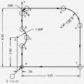
In this cnc program block no. N35 to N50 (points 2-3, 3-4, 4-5) are in straight movement (Linear Interpolation) and for that propose we have the CNC G-Code G01 (linear interpolation),
Point 5-6 is not possible with G01 code because tool is not going straight, tool is traveling in a circular way, for this purpose cnc machinists have circular interpolation codes G02/G03.
Before using G02/G03 G code cnc machinists must know the exact values of
(1) End-point
(2) Radius between start to end points.
So the required values at point 6 are
(1) X=70, Y=65 (as End-point)
(2) R=15 (as Radius).
After getting this information we are now in the position to write the CNC program block code for point 5 through 6.
First circular motion G02-G03, Second is End-point X, Y values and the Third is R (Radius), in this way we can achive our required results.
Point 6-7 is again linear and point 7-8 is circular motion, so do the same as stated above but before writing the code, check the motion direction whether it is clockwise or counter clockwise, and this motion is clockwise, so use the code G02.
After that the other points are linear movements.
Every linear motion is cancelled by the circular motion (G01 is cancelled by G02/G03) and every circular motion is cancelled by the linear motion (G02/G03 is cancelled by G01)
Incremental Dimensioning System Program
Here is the same cnc program but with G91 Incremental Dimensioning System.
N35 G42 X0 Y0 M08 	(Liner motion)
N40 G91 X60 Y0  	(Liner motion)
N45 X25 Y30 		(Liner motion)
N50 X0  Y20 		(Liner motion)
N55 G03 X-15 Y15 U15	(Circular motion G03 for Counter Clockwise motion and U for arc radius)
N60 G01 X-25 Y0  	(Liner motion)
N65 G02 X-15 Y-15 U15	(Circular motion G02 for Clockwise motion and U for arc radius)
N70 G01 X-20 Y0 	(Liner motion)
N75 X-10 Y-50  		(Liner motion)
Explanation of CNC G-Code/M-Code/S, F, D
G00 : Rapid traverse.
G54 : Zero Offset no. 1.
G64 : Continuous-path mode.
G90 : Absolute dimensioning system.
G17 : X-Y plan selection.
G42 : Cutter radius compensation activation (right hand side movement)
G40 : Cutter radius compensation de-active
G02 : Circular Interpolation clockwise
G03 : Circular Interpolation anti-clockwise (counter clockwise)
S : Spindle speed
F : Axis motion feed
M : Cutter motion (3=clockwise, 4=anti-clockwise)
D : Tool no
M08 : Coolant on
M09 : Coolant off
M30 : End of main program