Contents
Osai UGS (UCG) – Use Graphic Scale (Machine plot)
Osai 10 Series UGS command initialises the graphic display and establishes the limits and the orientation of the graphic display.
Programming
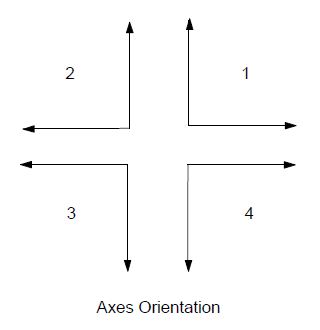
(UGS [,ax-orient],abs-axis,val1,val2,ord-axis,val3,val4 [,third-axis])
Parameters
| Parameter | Description |
|---|---|
| ax-orient | Is a number (from 1 to 4) that selects the type of axis orientation (see figure). The default value is 1 |
| abs-axis | Is the name of the abscissa on the display |
| val1 | Is the lower limit of the abscissa |
| val2 | Is the upper limit of the abscissa |
| ord-axis | Is a name of the ordinate on the display |
| val3 | Is the lower limit of the ordinate |
| val4 | Is the upper limit of the ordinate |
| third-axis | Is the name of the third axis (generally a spindle axis). |
Examples
(UGS,1,X,100,150,Y,50,250,Z)
The graphic display shows movements between X100 and X150 on the abscissa and between Y50 and Y250 on the ordinate referred to the current origin.
Osai UGS (UCG) – Use 3D Graphic Scale
Programming
(UGS ,5,axis1,val1,val2,axis2,val3,val4,axis3,val5,val6 [ , ])
Parameters
| Parameter | Description |
|---|---|
| 5 | Selects 3D graphic scale |
| axis1,axis2,axis3 | Are the names of the three axes to be displayed |
| val1,val2 | Lower and upper limit of the first axis |
| val3,val4 | Is the upper limit of the abscissa |
| α | α angular parameter It is the rotation angle to be applied to the horizontal plane during the 3D the display. The typical horizontal plane is XY. |
| β | β angular parameter. It is the rotation angle to be applied to the vertical plane during 3D display. Typical vertical planes are XY or XZ. |
Note
α and β parameters are optional. If they are omitted ,the system will take by default:
α = 30°
β = 30°


