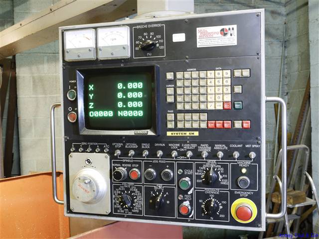
Fanuc 6 Alarm Codes applies to Fanuc System 6M 6T CNC controls. For cnc machinists who work on cnc lathe with 6T or CNC mill with Fanuc 6M cnc control.
Fanuc System 6M and 6T Alarm codes are divided as below
- 210 to 245 Errors on stroke end limit switches
- 400 to 445 Errors on Servo System
- 600 to 603 Errors on PCB or Cables
- 700 to 702 Overheat of section or motor
- 900 to 999 Errors on Memory
Contents
Fanuc 6M / 6T Alarm Codes
Program Errors or Operator’s Errors
| Alarm | Alarm Description |
|---|---|
| 000 | Re-apply the power after the parameter has been input |
| 001 | TH Alarm (A character with incorrect parity was input) Correct the tape |
| 002 | TV Alarm (The number of characters in a block is odd). This alarm will be generated only when the TV check is effective |
| 003 | Data exceeding the maximum allowable number of digits was input |
| 004 | A numeral or the sign (-) was input without an address at the beginning of the block |
| 005 | The address was not followed by the appropriate data but was followed by another address of EOB code |
| 006 | Sign “-” input error (sign “-” was input after a address with which it can’t be used. Or two “-” signs were used). |
| 007 | Decimal Point “.” Input error (A decimal point was input after a address with which it can’t be used. Or two decimal points were input). |
| 008 | The switch position of the tape reader was not AUTO (without reel) or REEL ON/REEL OFF (with reels). |
| 009 | Unusable character was input. (E). |
| 010 | A unusable G code was commanded. (The alarm is generated also when a G code with which the control is not equipped as an option is commanded). |
| 011 | Feedrate was not commanded at cutting feed or the feedrate was inadequate |
| 015 | The number of the commanded axes exceeded that of the allowable simultaneously controlled axis |
| 017 | The move commanded of the additional axis was commanded without equipping with an optional additional axis. |
| 018 | An additional axis was commanded with the other axis simultaneously. |
| 021 | The axis not included in the selected plane (by using G17, G18, G19) was commanded in circular interpolation. |
| 022 | In circular interpolation, radius designation was performed in the NC which is not equipped with the radius designation option. |
| 023 | In circular interpolation by radius designation, Zero was commanded for address R. |
| 030 | The tool offset number is too large for the D or H function. |
| 031 | In setting of offset amount by G10, The offset number following address P was excessive or it was not specified. |
| 032 | In setting of offset amount by G10, the offset amount was excessive. |
| 035 | Skip Cutting (G31) was commanded in cutter compensation mode. |
| 036 | G45-G48 (Tool Offset) was commanded in cutter compensation mode. |
| 037 | The selected (by using G17, G18 or G19) changed in cutter compensation mode. |
| 038 | Over cutting will occur in cutter compensation because the arc start point or end point coincides with arc center |
| 041 | Overcutting will occur in cutter compensation. |
| 044 | One of G27-G30 was commanded in canned cycle mode. An ATC cycle (M06) was commanded in canned cycle mode. |
| 045 | An ATC cycle (M06) was commanded for the NC which is not equipped with optional reference point return feature. |
| 046 | Other than P2, P3 and P4 was specified in the 2nd, 3rd and 4th reference point return commands. |
| 047 | G27 to G30 was commanded for and axis which does not have a reference point. |
| 058 | In 4-digit S code binary 12-bit/analogue output A, A command was specified exceeding the maximum or minimum number of spindle revolutions. |
| 059 | No program for selected work number is found (external work number select A function). |
| 060 | Commanded sequence number was not found in the sequence number search, |
| 065 | Scaling Magnification was specified as other than 1-99999. |
| 066 | Scaling was applied and as a result, movement value, coordinate value, circular arc radius, etc. exceed maximum programmable dimension. |
| 067 | G51 (scaling ON) was specified in cutter compensation mode. |
| 070 | The Fanuc memory area is insufficient. |
| 071 | The address to be searched was not found. |
| 072 | The number of programs to be stored exceeds 95 or 191. (191 is a option). |
| 073 | The program number has already been used. |
| 074 | The program number is other then 1-9999 |
| 075 | The program number or sequence number was not found at the start block of the program |
| 076 | The address P was commanded in the block with includes a M98 command. |
| 077 | The subprogram was called in triple |
| 078 | The sequence number which was specified by address P in the block which includes a M98 or M99 was not found |
| 079 | Memorized program and tape contents do not coincide |
| 085 | When storing data in memory by using ASR or RS232C interface, an over-run or framing error was generated |
| 086 | The signal level of RS232C interface was incorrect |
| 087 | When storing data in the memory by using the Fanuc RS232 interface, the time required to store the data is insufficient. |
| 090 | The reference point return cannot be performed normally because the reference point return start point is to close to the reference point or one revolution signal is not input owing to a fault in the pulse coder. |
| 091 | Reference point return cannot be executed normally, because of the feedrate is too low to synchronise the one revolution signal of the pulse coder with the reference counter, |
| 092 | The axis designated by G27 did not return to reference point. |
| 094 | No P type can be specified for program restart (because after program interruption, coordinate system setting or ORIGIN, etc. was executed) |
| 095 | No P type can be specified for program restart (because after program interruption, external work zero point offset value changed) |
| 096 | No P type can be specified for program restart (because after program interruption, work zero point offset value changed). |
| 097 | No P type can be specified for program restart (because after program interruption, no automatic operation has been executed). |
| 100 | The switch to set parameters is on. Push the reset button after turning off the switch. |
| 101 | The power was turned off while rewriting the contents of memory in the part program storage & editing operation. When this alarm is generated you must turn on the power while pushing the DELETE and RESET buttons to clear the memory. |
| 110 | Absolute value of data of fixed point representation exceeds the upper bound (99999999). |
| 111 | Exponent of data of floating point representation exceeds the upper bound. |
| 112 | Divisor is 0 |
| 113 | A function that cannot be used by user macro A is used |
| 114 | Format error except for |
| 115 | Value not defined as variable number is assigned |
| 116 | Left side of substituted sentence is a variable of prohibited substitution |
| 118 | Nesting of brackets exceeds the upper limit (5). |
| 119 | Argument of SQRT is negative , Or argument of BCD is negative |
| 122 | Nesting of macro exceeds the upper limit (4) |
| 123 | Macro control command is uded in tape mode |
| 124 | DO END is not 1:1 corresponding |
| 125 | Format error of (formula) |
| 126 | Not 1 £ n £ 3 in DO n |
| 127 | NC command and macro command are mixed |
| 128 | Not 0 £n £9999 in GO TO n |
| 129 | Unallowable address is used in . |
| 130 | In external data input, greater-address data contains an error |
| 131 | In external alarm message, five or more alarms have occurred |
| 132 | In external alarm message, clear, no corresponding alarm number exsists |
| 133 | In external alarm message and in external operator message, smaller- address data contains an error |
| 170 | Programs of numbers 8000 – 8999 and 9000 – 9899 are being edited, But this alarm occurs only when parameter setting inhibits these programs to be edited. |
Errors on Stroke Limit Switch
| Alarm | Alarm Description |
|---|---|
| 210 | The movable part of machine touched the X Axis plus stroke limit switch |
| 211 | The movable part of machine touched the X Axis minus stroke limit switch |
| 212 | While the X Axis was moving in the plus direction, It entered into the forbidden area of the stored stroke limit 1 |
| 213 | While the X Axis was moving in the minus direction, It entered into the forbidden area of the stored stroke limit 1 |
| 214 | While the X Axis was moving in the plus direction, It entered into the forbidden area of the stored stroke limit 2 |
| 215 | While the X Axis was moving in the minus direction, It entered into the forbidden area of the stored stroke limit 2 |
| 220 | The movable part of the machine touched the Y axis plus stroke limit switch |
| 221 | The movable part of the machine touched the Y axis minus stroke limit switch. |
| 222 | While the Y axis was moving in the plus direction, it entered into the forbidden area of the stored stroke limit 1 |
| 223 | While the Y axis was moving in the minus direction, it entered into the forbidden area of the stored stroke limit 1 |
| 224 | While the Y axis was moving in the plus direction, it entered into the forbidden area of the stored stroke limit 2 |
| 225 | While the Y axis was moving in the minus direction, it entered into the forbidden area of the stored stroke limit 2 |
| 230 | The movable part of the machine touched the Z axis plus stroke limit switch |
| 231 | The movable part of the machine touched the Z axis minus stroke limit switch |
| 232 | While the Z axis was moving in the plus direction, it entered into the forbidden area of the stored stroke limit 1 |
| 233 | While the Z axis was moving in the minus direction, it entered into the forbidden area of the stored stroke limit 1 |
| 234 | While the Z axis was moving in the plus direction, it entered into the forbidden area of the stored stroke limit 2 |
| 235 | While the Z axis was moving in the minus direction, it entered into the forbidden area of the stored stroke limit 2 |
| 240 | The movable part of the machine touched the 4th axis plus stroke limit switch |
| 241 | The movable part of the machine touched the 4th axis minus stroke limit switch |
Errors on Servo System
| Alarm | Alarm Description |
|---|---|
| 400 | The control received the X, Y or Z axis overload signal |
| 401 | The READY signal (VRDY) of the X, Y or Z axis velocity control has turned off |
| 402 | The control received the 4TH axis overload signal |
| 403 | The READY signal (VARY) of the 4TH axis velocity control has turned off |
| 404 | The READY signal (VARY) of the X, Y or Z axis velocity control does not turn off even though the READY signal (PRDY) of the position control has turned off. The READY signal (VARY) of velocity control already on even though the READY signal (PRDY) of the position control is off yet at power on condition |
| 405 | In reference point return, reference point return is not performed in correctly by abnormality of NC control section or servo system. Perform manual reference point return again |
| 410 | The content of error register of the X axis is larger than the value allowed while the machine is stopped |
| 411 | The content of error register of the Y axis is larger than the value allowed while the machine is moving |
| 412 | Drift in X axis is excessive. (Exceeds 500VELO) |
| 413 | The content of the error register of the X axis exceeded =32767. Or the velocity command value of the DA converter is out of the range of +8191~ – 8192. Incorrect settings will cause this alarm |
| 414 | The resolver/inductosyn position detecting system of X axis is trouble |
| 415 | A feed rate exceeding 511875 detection units/sec was commanded in the X axis An incorrect setting of CMR causes this error |
| 416 | X axis pulse coder position feedback is abnormal. (Disconnection alarm) |
| 420 | The content of the error register of the Y axis is larger than the value allowed while the machine is stopped |
| 421 | The content of the error register of the Y axis is larger than the value allowed while the machine is moving |
| 422 | Drift in Y axis is excessive. (Exceeds 500VELO) |
| 423 | The content of the error register of the Y axis exceeded =32767. Or the velocity command value of the DA converter is out of the range of +8191~ – 8192. Incorrect settings will cause this alarm |
| 424 | The DSCG position detecting system of the Y axis is trouble |
| 425 | A feed rate exceeding 511875 detection units/sec was commanded in the Y axis An incorrect setting of CMR causes this error |
| 426 | Y axis Fanuc pulse coder position feedback is abnormal. (Disconnection alarm) |
| 430 | The content of the error register of the Z axis is larger than the value allowed while the machine is stopped |
| 431 | The content of the error register of the Z axis is larger than the value allowed while the machine is moving |
| 432 | Drift in Z axis is excessive. (Exceeds 500VELO) |
| 433 | The content of the error register of the Z axis exceeded =32767. Or the velocity command value of the DA converter is out of the range of +8191~ – 8192. Incorrect settings will cause this alarm |
| 434 | The resolver/inductosyn position detecting system of Z axis is trouble |
| 435 | A feed rate exceeding 511875 detection units/sec was commanded in the Z axis An incorrect setting of CMR causes this error |
| 436 | Z axis pulse coder position feedback is abnormal. (Disconnection alarm) |
| 440 | The content of the error register of the 4TH axis is larger than the value allowed while the machine is stopped |
| 441 | The content of the error register of the 4TH axis is larger than the value allowed while the machine is moving |
| 442 | Drift in 4TH axis is excessive. (Exceeds 500VELO) |
| 443 | The content of the error register of the 4THaxis exceeded =32767. Or the velocity command value of the DA converter is out of the range of +8191~ – 8192. Incorrect settings will cause this alarm |
| 444 | The resolver/inductosyn position detecting system of the 4TH axis is trouble |
| 425 | A feed rate exceeding 511875 detection units/sec was commanded in the 4TH axis An incorrect setting of CMR causes this error |
| 426 | Additional axis pulse coder position feedback is abnormal. (Disconnection alarm) |
Errors on PCB or Cables
Connection alarm between each PCB
| Alarm | Alarm Description |
|---|---|
| 600 | Data transferring error took place in the connection unit or in PC-model C |
| 601 | Slave relay was turned off. (Connections among unit, MDI/DPL (MDI/CRT) and master PCB are trouble. Another case change connection unit) |
| 602 | PC program has not yet been loaded |
| 603 | The correspondence between NC and PC is incorrect or interrupted. Change power sequence control PCB or master PCB |
| 604 | No hold is effective to PC-model B side MPU |
| 605 | A system error has occurred in PC-model B side MPU |
| 606 | RAM/ROM parity has occurred in PC-model B side MPU |
| 607 | Data transferring error took place in Fanuc MDI & CRT |
Overheat Alarms
Overheat of section or motor
| Alarm | Alarm Description |
|---|---|
| 700 | Overheat of the master PCB |
| 701 | Overheat of the PCB for 4TH axis |
| 702 | Overheat of DC motor for X, Y, Z axis |
| 703 | Overheat of DC motor for 4TH axis |
Errors on Memory
| Alarm | Alarm Description |
|---|---|
| 900 | Fault in bubble device. (Fault of input signal for bubble device) |
| 901 | Fault in bubble device. (The initial point in the bubble was not detected immediately after power on) |
| 902 | Fault in bubble device. (Page size error, undefined command) |
| 903 | Fault in bubble device. (Transfer missing, page size over) |
| 904 | Fault in Fanuc bubble device. (Parity error) |
| 905 | Fault in bubble device. (No marker) |
| 906 | Fault in bubble device. (Many defect loops) |
| 910 | RAM parity error (low byte) |
| 911 | RAM parity error (high byte) |
| 920 | System error (watch dog timer alarm) |
| 930 | CPU error (0, 3, 4 type interrupt generation) |
| 997 | ROM parity error (PC ROM) |
| 998 | ROM parity error (Basic ROM) |
| 999 | ROM pair error (No correspondence between high and low) |


