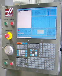
Haas Setting 143 Machine Data Collect
Haas Setting Description
This setting enables the user to extract data from the control using a Q command sent through the RS-232 port. See manual section “Loading Programs to the CNC Control” for information on RS-232 cables
This feature is software-based and requires an additional computer to request, interpret and store data from the control. Note that the control will only respond to a Q command when this setting is ON. The following output format is used:
<STX> <CSV response> <ETB> <CR/LF> <0x3E> (“CSV” means Comma Separated Variable that is a line of information in which each piece of information is separated from the next with a comma). Note: STX = 0x02 (ctrl-B); ETB = 0x17 (ctrl-W).
If the control is busy, the control will output “STATUS, BUSY.” If a request is not recognized, the control will output “UNKNOWN.”
The following commands can be used:
Q100 – Machine Serial Number
Q101 – Control Software Version
Q102 – Machine Model Number
Q104 – Mode (LIST PROG, MDI, MEM, JOG, etc.)
Q200 – Tool Changes (total)
Q201 – Tool Number in use
Q300 – Power-on Time (total)
Q301 – Motion Time (total)
Q303 – Last Cycle Time
Q304 – Previous Cycle Time
Q400 – not currently used
Q401 – not currently used
Q402 – M30 Parts Counter #1 (resettable at control)
Q403 – M30 Parts Counter #2 (resettable at control)
Q500 – Three-in-one (PROGRAM, Oxxxxx, STATUS, PARTS, xxxxx)
Q600 Macro or system variable
The user has the ability to request the contents of any macro or system variable by using the Q600 command, for example, “Q600 xxxx” where xxxx is the macro variable.
In addition, Macro variables #1-33, 100-199, 500-699, 800-999 and #2001 thru #2800 can be “written to” using an “E” command, for example, “Exxxx yyyyyy.yyyyyy” where xxxx is the macro variable and yyyyyy.yyyyyy is the new value. Note that this command should only be used when there are no alarms present.
Status Relays Special Additional Remote Machine Data Collection.
This feature can be accomplished with the installation of the following optional parts: 8 Spare M-code relay board (all 8 become dedicated to below functions and can no longer be used for normal M-code operation), a power-on relay, an extra set of Emergency Stop contacts, and a set of special cables; contact your dealer for pricing information on these parts.
Once installed, output relays 40 thru 47, a power-on relay and the Emergency Stop switch are used to communicate the status of the control. Note: Parameter 315 bit 26 “STATUS RELAYS” must be enabled. Standard spare M-codes are still available for use.
The following communications will be received (* are only available when used with the optional parts):
* E-STOP contacts. This will be closed when the E-STOP button is pushed.
* Power ON – 115 VAC. Indicates that the control is turned ON. It should be wired to a 115 VAC coil relay for interface.
* Spare Output Relay 40. Indicates that the control is In-Cycle (running.)
* Spare Output Relay 41 and 42:
11 = MEM mode & no alarms (AUTO mode.)
10 = MDI mode & no alarms (Manual mode.)
01 = Single Block mode (Single mode)
00 = other modes (zero, DNC, jog, list prog, etc.)
* Spare Output Relay 43 and 44:
11 = Feed Hold stop (Feed Hold.)
10 = M00 or M01 stop
01 = M02 or M30 stop (Program Stop)
00 = none of the above (could be single block stop or RESET.)
* Spare Output Relay 45 (Feed Rate Override is active and Feed Rate is NOT 100%)
* Spare Output Relay 46 (Spindle Speed Override active and Spindle Speed is NOT 100%)
* Spare Output Relay 47 (Control is in EDIT mode).
References
- Haas Lathe Operator’s Manual by Haas Automation, Inc.
- Haas Mill Operator’s Manual by Haas Automation, Inc.

