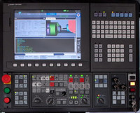
Okuma Alarm-B 2565 Load monitor system variable
In the Load-monitor specification,
1)BASE or 1st-limit,2nd-limit of the axis which does not exist for the Load-monitor was about to be read or write.
2)In the state of “ORDER:NG”, VOLPR was ordered.
3)Concerning Sub spindle-tailstock Control specification, it instructed with the instruction prohibited.
Object
SYSTEM
Code
1->System-variable “VLMYB”,”VLMY1″,”VLMY2″ was used on the side of B-turret(G14).
2->In the mathine that was not the Multiple-Machine specification, System-variable “VLMCB”,”VLMC1″,”VLMC2″,”VLMMB”,”VLMM1″,”VLMM2″ was used.
3->Though W-axis did not exist, System-variable “VLMWB”, “VLMW1″,”VLMW2” was used.
4->Though the 2nd-spindle did not exist, System-variable “VLMBB”,”VLMB1″,”VLMB2″ was used.
5->Though Y-axis did not exist, System-variable “VLMYB”, “VLMY1″,”VLMY2” was used.
6->Though M-axis did not exist on the B-turret, System-variable “VLMMB”,”VLMM1″,”VLMM2″ was used on the side of B-turret(G14).
9->The spec of Tool retraction cycle.
10->The state A-side was “VLMON != 0”, and B-side was “VLMON != 0”, VOLPR was used.
Measures to Take
1)Program error
Load-monitor specification:
There are System-variable that cannot be used by the machine-spec. on System-variable for Load-monitor.
Deleate the System-variable for Load-monitor that cannot be used.
It is ordered “VOLPR” in correct block.

