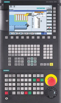
Sinumerik Alarm 21612 Channel %1 axis %2 VDI signal ‘Servo enable’ reset during motion
Parameters:
%1 = Channel number
%2 = Axis name, spindle number
Definitions:
The interface signal “Servo enable” (DB31 – 48, DBX 2.1) has been set to 0 for the dis- played axis even though one of the axes in the geometry grouping was in motion. The axes entered in the channel-specific MD array 20050 AXCONF_GEOAX_ASSIGN_TAB count as axes belonging to the geometry grouping. Servo enable must exist for all available geometry axes, regardless of whether they are currently in motion or not. Occurs in connection with SAFETY function: If a test stop is performed with linked axes, the alarm is issued if a motion command from the ELT grouping is pending during the test stop of the slave axis.
Reactions:
– NC Start disable in this channel.
– Alarm display.
– Interface signals are set.
– NC Stop on alarm.
– The NC switches to follow-up mode.
– If the axis is a single axis when this alarm is triggered, the alarm is only effective for this axis (not effective for e.g. the channel or mode group)
Remedy:
Please inform the authorized personnel/service department. Check the interface signal “Servo enable” (DB31 – 48, DBX 2.1, e.g. with the PLC status display in the DIAGNOS- TICS operating area). Trace back the signal to the sections in the PLC user program at which it is linked and set/reset. With SAFETY: With active actual-value linkage, the output of the error message on the slave axis can be prevented by increasing MD 36060 $MA_STANDSTILL_VELO_TOL to 100 and 200 (default value is 5 mm).
Program Continuation:
Clear alarm with the Delete key or NC START.
References
- Siemens Diagnostics Guide by Siemens

